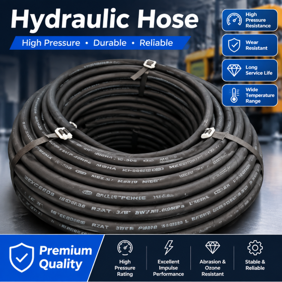
Fire Resistant Hydraulic Hose – Stainless Steel Armored, High Pressure
1. Product Definition and Application Scope
Fire resistant hydraulic hoses with stainless steel armor represent a specialized category of flexible fluid power transmission products engineered for high-risk environments where both pressure containment and fire survival are mandatory. These hoses are extensively deployed on drilling rigs and offshore platforms as critical components in well control systems, specifically serving as the flexible control lines that transmit hydraulic power from surface or subsea control units to blowout preventers (BOPs), diverters, and associated wellhead safety valves.
Unlike standard hydraulic hoses used in general industrial applications, this product category must simultaneously satisfy three demanding performance criteria: the ability to contain high-pressure hydraulic fluid without leakage under cyclic loading, the capacity to withstand direct flame impingement for a defined duration without loss of integrity, and the structural durability to survive the harsh marine environment including saltwater corrosion, ultraviolet exposure, and mechanical abrasion from rig operations.
The product is governed by a suite of international standards. API Spec. 16D (Control Systems for Drilling Well Control Equipment) provides the primary framework for design, testing, and certification, with particular emphasis on fire resistance validation. API 7K (Drilling and Well Servicing Equipment) addresses general equipment requirements. Lloyd‘s Register Fire Test Procedure sets the specific test methodology for the 704°C flame exposure. For subsea applications, API 16C (Flexible Pipe Systems) provides additional guidance on fatigue life and dynamic performance. In environments where hydrogen sulfide is present, NACE MR0175 / ISO 15156 governs material selection for sulfide stress cracking resistance.
2. Structural Architecture and Engineering Design
The fire resistant hydraulic hose is constructed as a multi-layer composite system, with each layer contributing specific functional attributes to the overall performance. The design philosophy prioritizes redundancy and progressive protection, ensuring that failure of any single layer does not immediately compromise the pressure boundary.
Inner Fluid Barrier Layer: This innermost layer is manufactured from a specialized rubber compound, typically Nitrile Butadiene Rubber (NBR) or Hydrogenated Nitrile Butadiene Rubber (HNBR). These materials are selected for their excellent resistance to petroleum-based hydraulic fluids, water-based fire-resistant fluids, seawater, and various drilling fluid additives that may enter the hydraulic system through contamination. The inner layer must maintain low permeability to prevent fluid migration into the reinforcement structure, which could lead to blistering or delamination. The compound formulation also incorporates additives for ozone resistance and thermal stability across the full operating temperature range.
Primary Reinforcement Layer: Surrounding the inner tube is a high-strength reinforcement structure composed of multiple layers of helically wound steel wire. The number of wire layers typically ranges from 2 to 8, depending on the required pressure rating and hose diameter. For high-pressure applications up to 15000 psi, a minimum of 4 layers of high-tensile wire is standard, with each layer applied at a specific lay angle to balance hoop stress containment and axial strength. The wire material is typically a high-carbon steel with tensile strength exceeding 2000 MPa, drawn to precise dimensions and coated with a bonding agent to ensure adhesion to the surrounding rubber layers. The helical winding geometry is carefully calculated to maintain sufficient flexibility while preventing kinking or collapse under pressure.
Intermediate Thermal Barrier Layer: Positioned between the reinforcement structure and the outer protective layers, this critical component consists of a refractory material designed to retard heat transfer. Common materials include ceramic fiber felts, intumescent composites that expand when heated to create insulating air gaps, or woven silica-based fabrics. The thermal barrier serves a dual purpose: it protects the inner pressure-retaining layers from external heat sources, and it maintains the reinforcement steel at temperatures below the threshold at which tensile strength degradation begins. The thickness and composition of this layer directly determine the hose’s fire survival time under specified test conditions.
Secondary Reinforcement and Anti-Collapse Layer: In hoses designed for subsea or high-external-pressure applications, an additional spiral-wound wire layer may be included between the thermal barrier and the outer cover. This layer resists external collapse forces from hydrostatic pressure at depth and provides additional hoop strength during rapid pressure transients.
Outer Protective Cover and Stainless Steel Armor: The exterior protection system consists of two components. The base cover is a flame-retardant synthetic rubber compound formulated with halogenated polymers or phosphorus-containing additives to resist ignition and slow flame propagation. Over this cover, a stainless steel armor layer is applied. The armor is typically constructed as either an interlocked or a spiral-wrapped configuration. The interlocked type consists of steel profiles that mechanically interlock to form a continuous flexible sheath, while the spiral-wrapped type uses multiple overlapping helically wound strips. The armor material is 316L stainless steel – a low-carbon, molybdenum-bearing grade selected for its superior resistance to pitting and crevice corrosion in seawater environments. The stainless steel armor provides mechanical protection against impact, abrasion, and cut-through; radiant heat reflection and thermal shielding; and structural support to prevent hose elongation or kinking under tension.
End Terminations: The hose ends are fitted with high-pressure connectors that must maintain pressure integrity at least equal to the hose rating. Attachment is achieved through swaging, crimping, or compression fitting processes, each requiring precise control of compression force to achieve the specified pull-out resistance. The connector materials are typically heat-treated alloy steel, and the entire fitting assembly is protected with fire-resistant sleeves or coatings to ensure the termination zone meets the same fire resistance standard as the hose body. Common fitting types include hammer unions, API flanged connections, threaded connectors, and customized terminations for umbilical integration.
3. Performance Specification and Technical Parameters
Pressure Ratings: The working pressure rating defines the maximum continuous operating pressure at a specified temperature. For high-pressure versions, ratings range from 5000 psi to 15000 psi, with some specialized products reaching 20000 psi for ultra-deep applications. The proof test pressure is typically 1.5 times the working pressure, and the minimum burst pressure is 3 times the working pressure, providing a substantial safety margin against overload conditions. These test pressures are verified on each production length as part of quality control.
Fire Resistance Performance: The industry benchmark fire resistance test is defined by API 16D and Lloyd’s Register procedure. The standard requirement is zero leakage when the hose assembly is exposed to an open flame at a temperature of 704°C ± 50°C while pressurized to the rated working pressure for a duration of 5 minutes. The test evaluates the complete assembly including end fittings, as these represent potential leak paths. Some offshore operating companies specify extended duration tests at 30 minutes or temperatures up to 1000°C for enhanced safety margins on critical wells. Successful fire testing must demonstrate that the hose maintains pressure throughout the exposure period and remains leak-free during a subsequent hydrostatic pressure retention test.
Temperature Capability: The standard operating temperature range for these hoses is -40°C to +100°C, which covers most drilling environments from Arctic conditions to tropical offshore operations. Specialized high-temperature versions are available with ratings up to +150°C for applications involving geothermal wells or high ambient temperatures in enclosed engine room areas. Low-temperature performance is equally important, as rubber compounds can become brittle and lose flexibility at sub-zero temperatures, potentially leading to cracking when the hose is flexed during handling or operation.
Flexibility and Bend Radius: The minimum bend radius is a critical design parameter that determines installation flexibility and operational durability. For a given hose diameter, smaller bend radii increase routing options but accelerate fatigue accumulation in the reinforcement wires. The specified minimum bend radius at working pressure is typically 20 to 25 times the hose diameter for spiral-wound reinforced constructions. During installation, a larger bend radius should be maintained to avoid residual stresses. The bend radius is also influenced by the presence and type of stainless steel armor – interlocked armor provides greater flexibility than spiral-wrapped armor but may offer slightly lower crush resistance.
Abrasion Resistance: The combination of stainless steel armor and flame-retardant rubber cover provides high resistance to mechanical wear from contact with rig structures, moving equipment, and handling operations. Armor thickness and material hardness are selected to balance protection against the need for flexibility and weight control.
Corrosion Resistance: The 316L stainless steel armor ensures long service life in marine atmospheres where salt spray and humidity accelerate corrosion of carbon steel. For critical applications, additional galvanic isolation between the stainless steel armor and carbon steel fittings may be specified to prevent bimetallic corrosion.
4. Rig and Offshore Platform Applications
Drilling Rig Well Control Systems: On land-based and jack-up drilling rigs, fire resistant hydraulic hoses are installed in the hydraulic control system that operates the BOP stack. The hoses connect the accumulator unit, control manifold, and the BOP actuators, providing the fluid pathway for closing and opening rams, annuli, and choke lines. In an emergency well control situation, the operator must have instantaneous hydraulic response, and the hoses must maintain function even if a rig fire occurs as a consequence of a kick or blowout. For this reason, the fire resistance requirement is not a theoretical specification but a genuine safety-critical feature.
Offshore Platform Applications: On fixed production platforms and tension-leg platforms, these hoses are used not only for drilling BOP control but also for production tree control systems, emergency shutdown valve actuators, and firewater system controls. The common thread is the need for reliable hydraulic operation during potential fire scenarios resulting from well fluid releases, equipment failures, or process upsets.
Subsea Deployment: For floating drilling vessels operating in deep water, the fire resistant hoses are often incorporated into subsea umbilicals that run from the surface vessel to the seabed BOP stack. In this configuration, the hose experiences both internal pressure and external hydrostatic pressure, as well as cyclic bending loads from vessel motion. The stainless steel armor is essential to prevent collapse under external pressure and to protect against abrasion during deployment and recovery operations.
Dynamic Positioning and Vessel Motion: On dynamically positioned drilling vessels, the hose undergoes continuous relative motion due to wave-induced vessel movement. This dynamic loading must be accounted for in fatigue analysis, and the hose construction should incorporate fatigue-resistant design features including optimized wire lay angles and low-hysteresis rubber compounds.
5. Regulatory Compliance and Quality Assurance
API Monogram: The API monogram is a recognized mark of quality and compliance for oilfield equipment. To obtain API monogram authorization for 16D, manufacturers must undergo a rigorous audit of their quality management system and product design records, including demonstration of test capabilities and traceability systems. The API Q1 specification defines the quality management system requirements.
Fire Test Certification: Complete documentation of fire test performance is mandatory for product acceptance. Test reports must include furnace temperature profiles, flame application methods, test assembly configurations, and pressure monitoring records. Third-party witnessing by recognized certification bodies is typically required for offshore projects.
Hydrostatic and Burst Testing: Every production length of hose must pass a hydrostatic proof test at 1.5 times working pressure without leakage or structural distress. Burst testing is performed on representative production samples to validate design assumptions and verify manufacturing consistency.
Material Traceability: Raw material certification is maintained for the rubber compounds, steel wires, steel armor, and connector components. Lot numbers and batch codes are recorded for each hose assembly, enabling complete traceability from mill to finished product.
Classification Society Certification: Major offshore operators require certification by recognized classification societies such as Lloyd’s Register, ABS, DNV, or Bureau Veritas. These certifications confirm that the product has been designed, manufactured, and tested in accordance with the applicable industry standards and the specific project requirements.
6. Selection and Specification Guidelines
Define Operating Conditions: The first step in selecting a fire resistant hydraulic hose is to establish the operating parameters. The maximum working pressure should be determined, including allowance for transient pressure surges. The expected temperature range at installation and in service should be specified, considering both ambient conditions and any heat sources in proximity to the hose routing.
Determine Fire Resistance Requirement: While the API 16D 5-minute/704°C requirement is the industry baseline, projects with higher risk profiles may specify extended duration ratings or higher temperature thresholds. These enhanced ratings affect cost and availability, so the selection should balance risk reduction against project economics.
Assess Environmental Factors: For subsea applications, external pressure at depth must be calculated and compared with the hose collapse resistance rating. For topside applications, exposure to chemicals, spray, and mechanical hazards should be evaluated. The presence of H₂S in the produced fluids must be considered for both internal fluid compatibility and external environment resistance.
Define Mechanical Requirements: The required hose length, routing, and bend radius should be determined based on equipment layout and installation access. The weight of the hose, including armor and fittings, must be evaluated for handling and support considerations.
Specify End Fittings: The type, size, and thread configuration of end fittings must match the mating hydraulic system components. Standard connections such as high-pressure hammer unions (Fig 1502, 2002), API flanges, or proprietary connections should be verified for compatibility.
Review Certification Package: The procurement specification should clearly list all required documents including test certificates, material certifications, and third-party inspection reports. This prevents delays during project acceptance and ensures that the supplied product meets the specified requirements.
7. Installation and Maintenance Practices
Handling and Storage: Stainless steel armored hoses should be handled with care to avoid impact damage to the armor and kinking of the hose structure. Storage areas should be clean, dry, and protected from direct sunlight, heat sources, and ozone-generating equipment. Hoses should be stored flat or on suitably sized reels to prevent deformation.
Routing and Support: The hose should be routed with adequate clearance from sharp edges, hot surfaces, and moving equipment. Support brackets or clamps should be used at appropriate intervals to prevent excessive sagging or vibration. The bend radius should be maintained above the specified minimum, especially near the end fittings where stress concentration is highest.
Inspection Schedule: A routine inspection program should include visual examination of the armor for damage, corrosion, or deformation; checking the cover and fitting areas for leaks; and verifying that support clamps remain secure. Any signs of armor cracking or rubber deterioration should trigger a more detailed evaluation.
Testing and Re-Certification: Periodic hydrostatic testing is recommended to confirm continued pressure integrity. The test pressure and frequency should be based on the manufacturer‘s recommendations and the criticality of the application. Hoses that have been subjected to severe service conditions, such as exposure to fire or extreme pressure transients, should be replaced or re-qualified before further use.
Replacement Criteria: Replacement is indicated under any of the following conditions: visual armor damage such as broken wires or deep gouges; leakage at fittings or through the hose body; exposure to fire beyond the rated duration; corrosion that has penetrated the armor; or service life exceeding the manufacturer’s recommended limit. Proactive replacement before the onset of visible degradation is generally the most cost-effective and safety-conscious approach.
