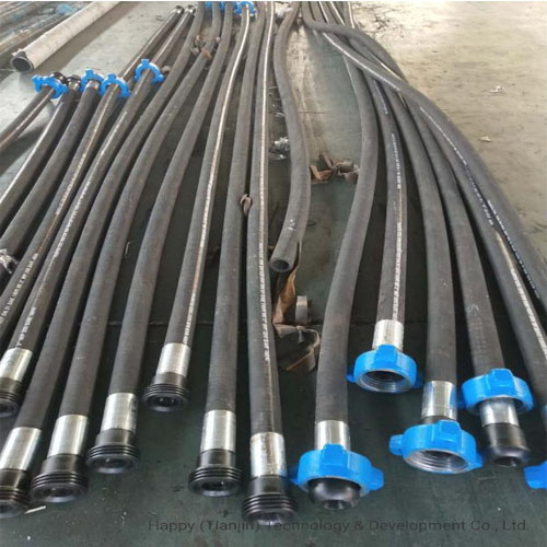
High-temperature fire-resistant flexible hose, BOP control line, flame-retardant rubber.
I. Product Positioning and Technical Standards
High-temperature fire-resistant hoses are key flexible components in the BOP (Blowout Preventer) control lines of well control systems. They are used to deliver hydraulic control media under high-pressure conditions, driving the opening and closing of the BOP gate and annular rubber core. Unlike conventional hydraulic hoses, this product must maintain pressure integrity and operational functionality under extreme accident conditions such as fires, providing a reliable time window for well control emergency response.
The core technical specification for this product is API Spec. 16D. This standard systematically regulates the design, manufacture, testing, and certification of BOP control systems. The fire resistance test procedure requires no leakage for 5 minutes under open flame conditions at 704℃±50℃. Some products also undergo supplementary verification with API 7K and classification society fire protection test procedures.
II. Structural Design and Material Composition
High-temperature fire-resistant BOP control hoses adopt a multi-layer composite structure. Each functional layer works together to meet the comprehensive requirements of high-pressure load-bearing capacity, fire protection, and corrosion resistance.
Inner Layer (Inner Rubber Layer): Primarily made of flame-retardant synthetic rubber, typically nitrile butadiene rubber (NBR) or hydrogenated nitrile butadiene rubber (HNBR). NBR exhibits good resistance to hydraulic oil, drilling fluid, and various chemical media; HNBR demonstrates superior performance in high-temperature aging and corrosion resistance, making it suitable for applications involving acidic media such as hydrogen sulfide (H₂S). The inner layer material must possess low permeability to prevent hydraulic media from penetrating to the reinforcing layer and causing interlayer separation.
Reinforcing Layer: Employs a multi-layered high-strength steel wire spiral winding structure, commonly 4 or 6 layers of high-strength, ultra-flexible steel wire. The number of wire layers is determined by the working pressure rating, with adjacent layers arranged alternately in winding direction to balance stress distribution in different stress directions. This structure achieves a balance between high-pressure load-bearing capacity and flexible bending, ensuring structural stability of the hose under rated working pressure.
Fire-resistant Insulation Layer: A fire-resistant insulation material is added between the reinforcing layer and the outer layer, forming a composite fire-resistant barrier. This first layer uses ceramic fiber or intumescent refractory composite materials, which expand under flame impact to form a heat-insulating carbon layer, delaying heat transfer to the internal pressure-bearing layer. The thickness and material of the refractory insulation layer directly determine the hose's fire resistance duration.
Outer Layer (Outer Rubber Layer): Made of high-temperature resistant, flame-retardant synthetic rubber, it directly withstands external environmental heat radiation and flame impact. Flame retardants are typically added to the outer rubber formulation to enhance resistance to flame spread. A stainless steel armor layer can be added to the outer layer, improving resistance to mechanical damage and, in a fire, reflecting heat radiation through the metal layer to delay heat transfer to the inner layer.
End Connections: Connections must use a crimping process, and the crimped area must be covered with fire-resistant tape or a metal sleeve to ensure the connection area also meets fire resistance requirements. Connection types include hammered unions and flanges, adaptable to different well control system interface types.
III. Key Performance Parameters
Operating Pressure: The typical operating pressure of a BOP control hose is 5000 psi (approximately 34.5 MPa). Some products cover a range from 5000 psi to 15000 psi to meet the needs of different well control systems.
Fire Resistance: The core performance indicator is no leakage for 5 minutes under open flame conditions at 704℃±50℃. Some products can withstand higher temperature conditions, but compliance determination is still based on the test conditions specified in API 16D.
Operating Temperature Range: The applicable ambient temperature under normal operating conditions is approximately -40℃ to +100℃. Some products can be extended to +121℃ or +150℃.
Corrosion Resistance: The inner layer material is resistant to hydraulic oil, drilling fluid, and weak acid and alkali media. In environments containing H₂S, an HNBR inner layer or stainless steel reinforcement layer solution must be selected to meet the requirements for resistance to sulfide stress corrosion.
Minimum Bending Radius: Depending on the hose's inner diameter, the minimum bending radius generally ranges from 300 mm to 800 mm, with a positive correlation to the nominal diameter.
Specification Series: Commonly used inner diameter specifications include 1/2 in, 3/4 in, 1 in, 1-1/2 in, and 2 in, covering various control circuit requirements from annular blowout preventers (BOPs) to gate blowout preventers (GEPs).
IV. Fire Resistance Mechanism and Technical Points The fire resistance performance of high-temperature fire-resistant BOP control hoses relies on the synergistic effect of multiple layers of materials. When an external flame impacts the hose, the stainless steel armor first reflects some heat radiation and prevents the flame from directly contacting the rubber layer; the outer flame-retardant rubber layer forms a carbonized layer under the influence of the flame, slowing down heat conduction; the ceramic fibers or expanded materials in the fire-resistant insulation layer further block the heat transfer path, ensuring that the reinforcing layer and inner layer remain within the tolerable temperature range within the specified fire resistance time.
The end joint area is a weak point in fire resistance performance. The thermal conductivity of the joint metal parts is much higher than that of the rubber layer, allowing heat to be rapidly conducted to the inside of the hose through the joint. Therefore, the crimping area of the joint must be covered with fire-resistant tape or a metal sheath to ensure that the joint has the same fire resistance as the pipe body.
V. Application Scenarios
Onshore Drilling Well Control Systems: Connects the hydraulic control unit to the blowout preventer (BOP) body, ensuring the BOP can operate normally in emergency situations such as fires, enabling emergency well shutdown.
Offshore Platform Well Control Systems: In offshore drilling platforms, control hoses must also withstand salt spray corrosion and dynamic operating loads, placing higher demands on the corrosion resistance and fatigue life of the materials.
Shale Gas and Deep-Sea Drilling: In high-pressure well control systems, hoses need to cover higher pressure ratings; some products can operate at pressures up to 15,000 psi.
Hydrogen Sulfide-Containing Conditions: In the development of acidic gas fields, control hoses must be resistant to sulfide stress corrosion cracking; the inner layer material is typically HNBR or stainless steel reinforced structure.
